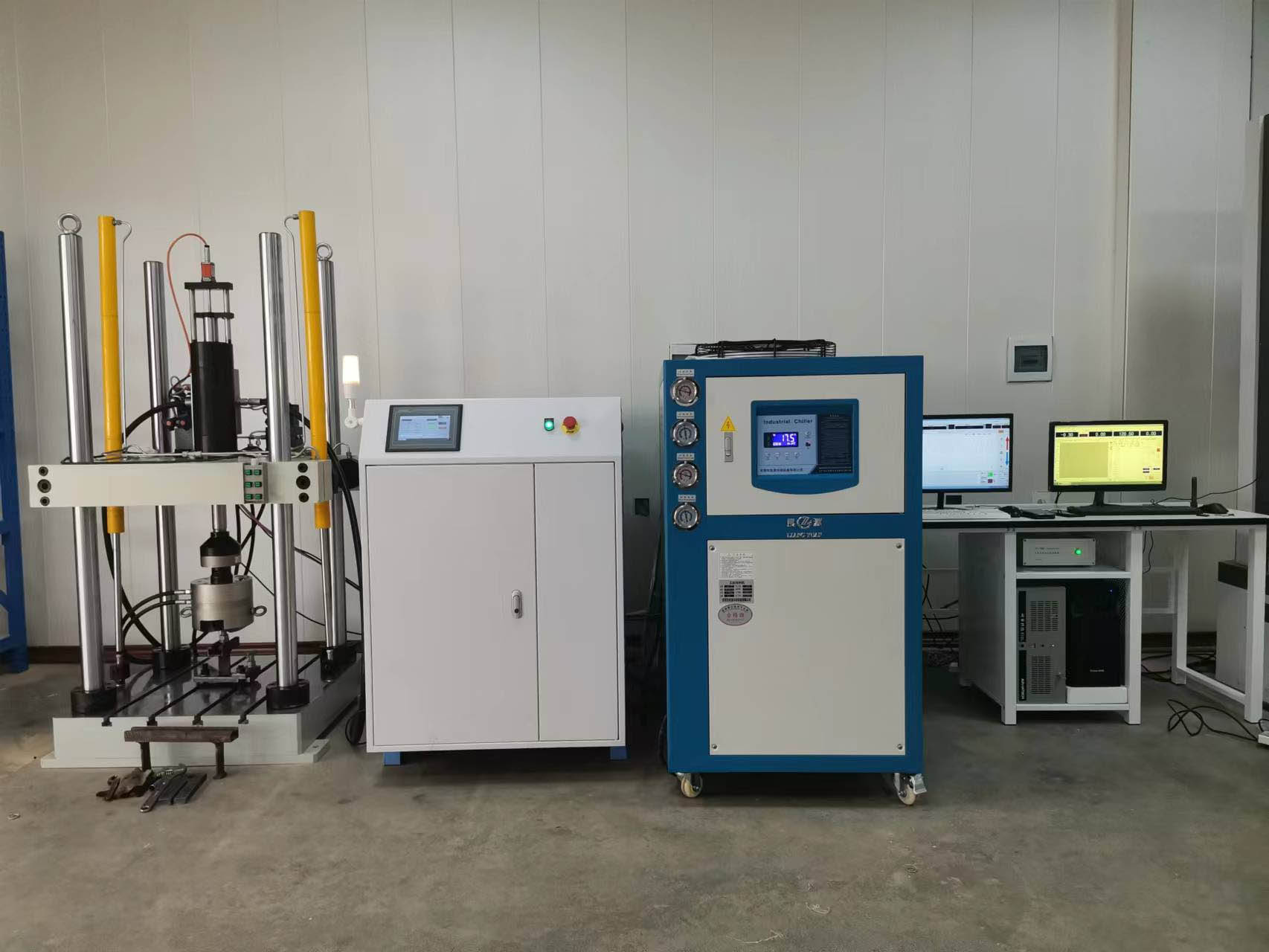
It is mainly composed of main frame, actuator assembly, lateral force loading device, control system and so on. The main machine adopts a four-column vertical structure, and the actuators are distributed up and down.
1. Product introduction
It is used for indicator test, speed characteristic test and durability test of various cylinder shock absorbers. The test and data processing methods meet the fatigue related requirements stipulated in QC/T491-1999 "Automobile cylinder Shock absorber size series and Technical Conditions",QC/T545-2007 "Automobile cylinder shock absorber bench Test Method" and other standards. The stiffness test and indicator test of elastomer in uniaxial direction can also be completed by replacing the fixture.
The test bench is designed and manufactured by electro-hydraulic servo control technology, which is mainly composed of main engine, full digital servo controller and necessary accessories for shock absorber test. It is suitable for fatigue test and performance test of automobile shock absorber under vertical load.
2. Main technical parameters and technical requirements
1. The maximum static test force: ±30KN;
Test force static measurement accuracy: ±0.5%; Measuring range: 1%-100%FS;
2. Maximum dynamic test force: ±30KN;
3. The maximum stroke of the actuator: ±150mm;
4. Displacement measurement accuracy: accuracy is ±1%FS;
5. Working frequency range: 0.1-10Hz;
6. Maximum test speed: 1.050m/s;
7. The maximum side force loading: 1500N, open loop control, under the conditions of the specimen piston rod can be arbitrarily set no more than 1500N loading value;
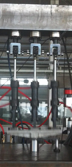
8. The number of test specimens at the same time of the test: one or two of the same specifications (but the total load cannot exceed the dynamic load that the test bench can bear)
During the performance test, the specimen is installed in the middle station, and the lateral force test can be loaded; During the fatigue test, two specimens of the same specification can be tested at the same time and installed on the stations on both sides.
9. Control mode: force, displacement two closed loop control loop, control mode can be smoothly switched.
10. Control system sampling frequency: 5KHz, closed-loop control frequency: 5KHz;
11. Full digital internal signal generator: sine wave, triangular wave, square wave, oblique wave, external input random wave, etc.
12. The control system can display test parameters (load, displacement real-time value, peak and valley value, working frequency, number of test cycles, etc.) and test curves in real time, and can record, store and output test parameters and curves;
13. The control system has automatic monitoring load, displacement, temperature (room temperature -120 ℃), protection of automatic alarm and automatic shutdown function;
14. Operating system Win7/10 platform, all Chinese operation interface; Man-machine interface is friendly, the working status is displayed through the display, and can display the current adjusted or monitored parameter status;
15. Data processing: computer screen display test parameters, automatically describe the test curve;
16. Axial test space: 160-1000mm, the distance between the center of the two fixtures; Internal static width of the column 500mm*500mm;
17. Sample cooling method: water cooling; The temperature of the cooling water inlet is not higher than 25 degrees, and the inlet flow of each shock absorber is not less than 20L/min. The pressure switch interface is reserved on the cooling water distributor, and the pressure switch is provided by the demander (when the water pipe breaks, the pressure will suddenly change, the pressure switch will send an alarm signal, and the control pump will stop working when the central control room receives the signal). The demander of the equipment should prepare the pressure quick shutdown by itself and inform the supplier of the interface size; Two sets of water jackets for a shock absorber are provided.
3. Objective conditions for equipment work:
1. Environment:
Ambient temperature: (10 ~ 40) ℃;
Relative humidity: ≤85%;
2, hydraulic system: the demander to provide power oil source and sub-station, sub-station filtration accuracy of 3 microns, through the flow of not less than 400L/min; The sub-station requires that the pressure can be adjusted and the pressure display; Viscosity range of hydraulic medium: ISO VS32~46; Oil temperature range: 15℃~55℃; Pipeline outlet hydraulic oil quality is less than or equal to NAS7.
The sub-station is provided with P (high pressure oil port, 2 inches), T (low pressure oil port, 2 inches), R (oil drain port, M18*1.5), wherein P port and T port are connected with SAE flange; Port R is threaded.
3, power requirements: AC220V/50Hz,2KW, the position is not more than 3 meters away from the installation position of the equipment; AC380V/50Hz,30KW, the position is not more than 3 meters away from the installation position of the equipment. The laboratory should have a good equipment line.
4, the equipment foundation requirements: the equipment is installed on the flat cement ground, the carrying capacity of not less than 4 tons per square meter.
5, the overall size of the equipment (length × width × height) : about 900mm×800mm×2350mm, the weight is about 1.6 tons.
4. Test bench function: The following tests can be completed:
1, damping test, measuring the damping force of the shock absorber;
2. Indicator test, draw the indicator diagram of shock absorber;
3. Speed characteristic test, measuring the temperature of shock absorber at each speed point under different loading speeds;
4, durability characteristics test;
5, lateral force performance sample.
6, shock absorber fatigue test; One or two fatigue tests can be achieved.
7. Road spectrum test;
8, can simultaneously calculate and display a number of continuous speed indicator diagram and resistance and speed curve; It can calculate and display the curve (P-V) of the relation between the displacement and the velocity of the shock absorber in a period when the shock absorber is moving at a single speed; It can calculate and display the graph of continuous change of sliding resistance under different lateral forces. All kinds of analysis results can be conveniently stored and called.
9, after the test can be automatically drawn force-displacement curve and force-velocity curve, its coordinates can be adjusted, damping force value results show that the maximum force value and maximum speed point (that is, the test stroke at the midpoint) force value, draw force-velocity curve can also choose the maximum force value of each speed point or the maximum speed point force value. It is possible to synthesize force-velocity curves for different time tests on a single graph.
10, can load 0 ~ 1.5kN side force, open loop control.
11. By replacing the tooling, the static stiffness test of rubber parts and the fatigue test of rubber parts can be realized; The displacement measurement of the static stiffness test adopts the displacement sensor of the host cylinder, and the tooling should ensure sufficient stiffness and strength. Load measurement adopts host load sensor; The fatigue test of rubber parts is only for fatigue test, and does not do other functional requirements.
5. Structure of the test bed
It is mainly composed of main frame, actuator assembly, lateral force loading device, control system and so on. The main machine adopts a four-column vertical structure, and the actuators are distributed up and down.
1, the main frame: by moving beam, workbench, guide column, locking mechanism composed of closed force frame
The frame is the bearing mechanism of the whole test bench. The actuator is placed under the table and above the beam; The moving beam is controlled by the lifting cylinder on both sides, and is locked by the hydraulic clamping cylinder. The lifting cylinder and the locking mechanism form an interlocking mechanism, which can adjust the test space stepless.
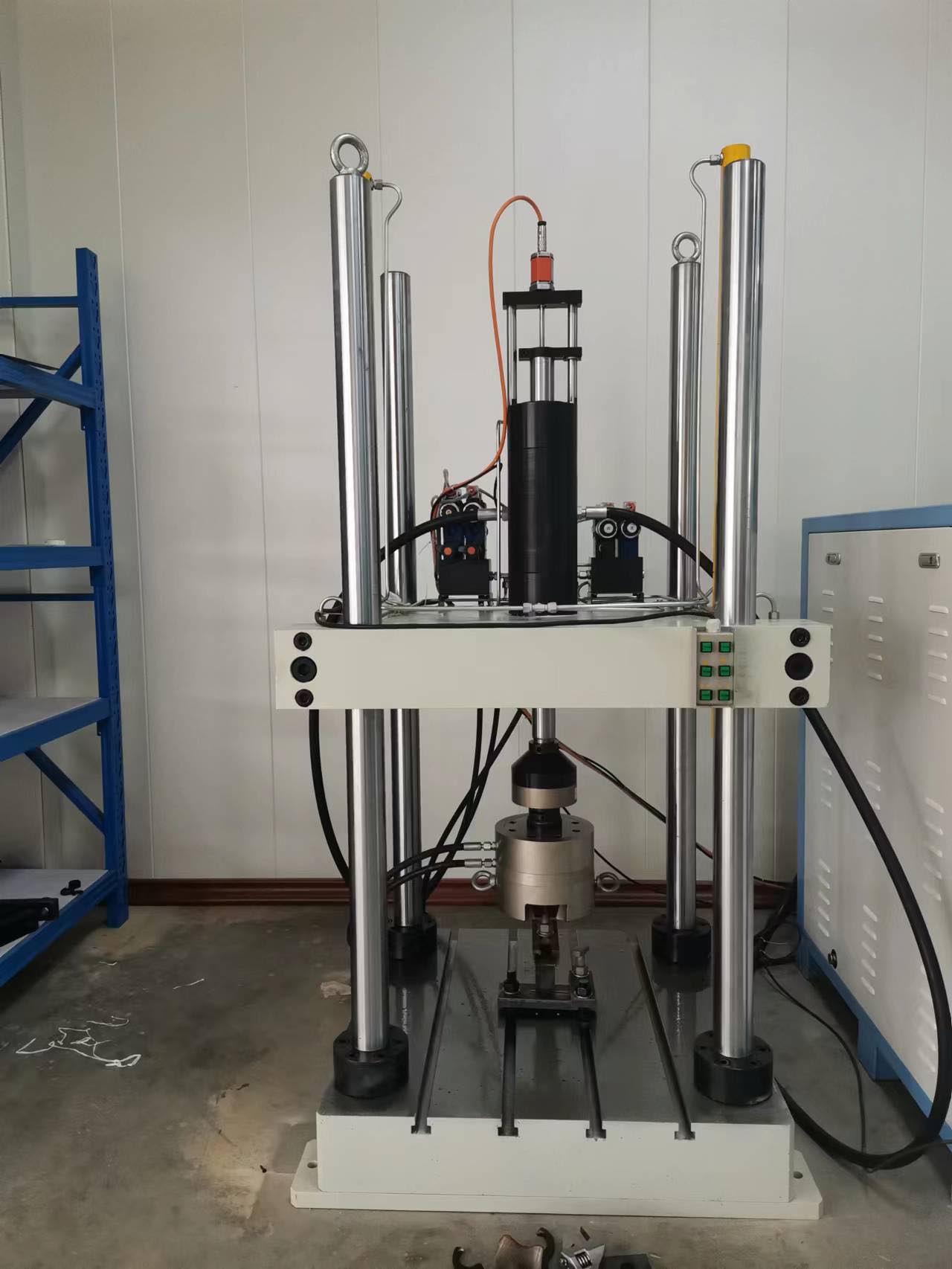
The moving beam and workbench are made of 45 steel. The surface of the guide column is plated with hard chromium to ensure the straightness and smoothness of the guide.
The surface of the column is plated with hard chromium, which is grinded and polished to ensure guiding accuracy, meet the axial stiffness requirements of dynamic tests, and have sufficient safety factor.
2. Servo actuator assembly: composed of servo hydraulic cylinder, displacement sensor, load sensor, servo valve, etc. It is a device that generates force and displacement in electro-hydraulic servo system, and is one of the key components. It adopts static pressure support guidance in design, and has low friction, low damping, high frequency noise and good resistance to lateral force.
The displacement sensor and piston rod are installed coaxial to ensure the accuracy of measurement. The standard configuration of this product is magnetostrictive displacement sensor
The load sensor adopts the wheel spoke type high-stiffness sensor produced by our company, which has high lateral force resistance and high frequency response, and can withstand 125% overload. The load sensor in the middle is used for performance measurement, the accuracy is guaranteed to be ±1%, the load sensor on both sides is used for protection monitoring, and the accuracy is not required. When a shock absorber fails, the load will change, and the test bench will automatically stop to avoid excessive lateral force damage to the equipment.
Servo valve: adopts the secondary servo valve of aerospace 609 Institute.
3, fixture: according to the specific samples or drawings provided by the demander design shock absorber special fixture,
6. Control system
The control system adopts suptest controller, which together with industrial control computer constitutes a complete servo control system. The characteristics of the controller are as follows:
1. The CPU adopts AMD520, 133Hz processor;
2. The control processor adopts 32-bit DSP chip
3. Full non-grading technology: the first non-grading technology high-resolution measurement system launched by the domestic testing machine industry has promoted the development of non-grading technology for measuring devices in the testing machine industry;
4. The minimum cycle of the control system is 0.0002s
5. High transmission rate: the first controller using Ethernet and USB dual interface in the domestic testing machine industry, users can choose the interface mode they need, and data transmission is stable and reliable;
6. High level of three closed loop control: the first domestic testing machine industry to achieve real load, deformation, displacement three closed loop control system, and smooth switching between different control modes;
7. Nonlinear correction technology: nonlinear correction technology is used for force and deformation sensors, which greatly improves the measurement accuracy of the whole machine;
CRIMS damper software interface (the diagram indicating power curve is for reference only)
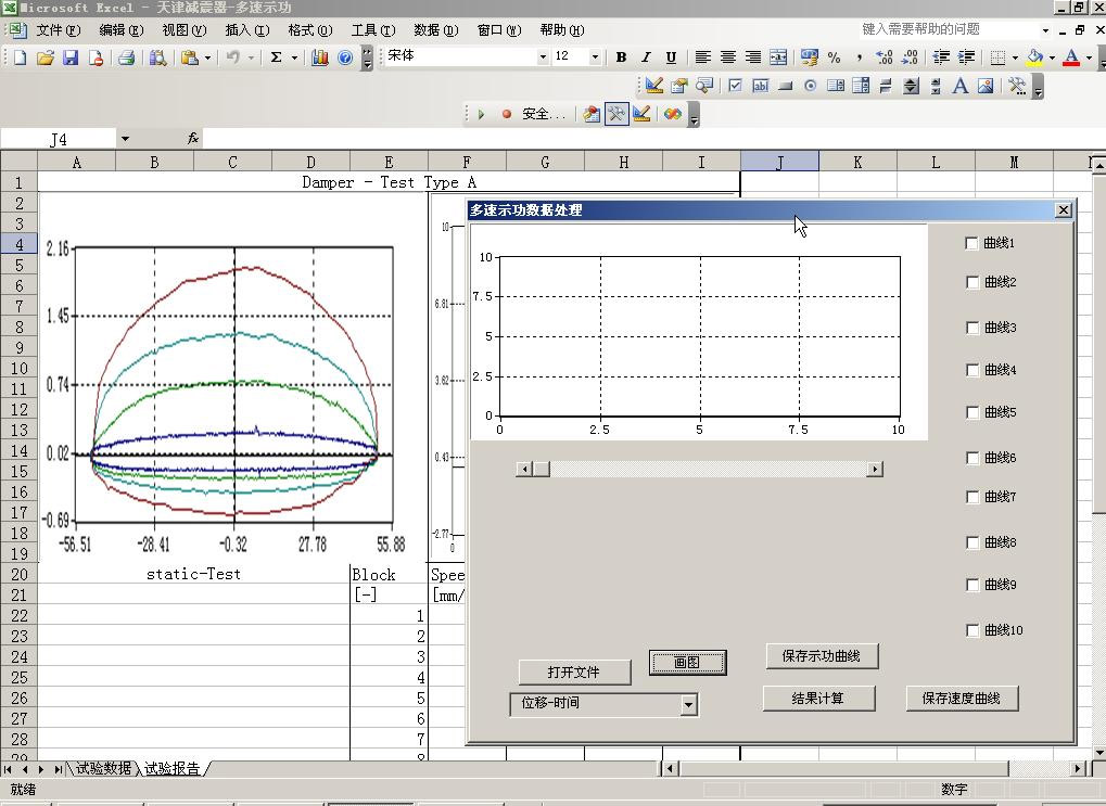
2) Computer operating system: The application software runs on the WINDOWS platform, and all operations are carried out on the Chinese virtual panel in the form of multi-task documents. The operation is intuitive and convenient, and the setting of test parameters and test conditions is easily completed. Test data can be imported into word, excel and other software for editing; Load and displacement have a variety of display modes, such as instantaneous value, peak and valley value, average value, etc. Directly display test frequency, fatigue times and other engineering quantities, print test results, test curves, etc.
7. Power source:
7.1 Constant pressure servo oil source
Constant pressure servo oil source common other equipment.
Servo oil source adopts closed quasi-silent design, the whole is counter type design. The oil source provides the pressure oil required for the movement of the main engine. Similar oil source photos below.
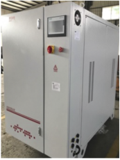
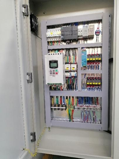
Figure 4 Closed intelligent oil source
7.2 Reliable component selection
The oil pump is imported internal gear pump, internal gear pump outstanding features are low noise, small hydraulic pulsation, long service life, very suitable for the dynamic fatigue testing machine hydraulic system conditions.
The motor is a famous brand products, the motor uses cast iron shell, strong vibration resistance, bearings are imported brands, stable operation, the overall anti-overload ability.
System high pressure hose assembly selected imported products, the product has a long service life, suitable for long-term use of high pressure system.
The main relief valve and electromagnetic directional valve are Shanghai Lixin products, and the filter selection of Liming hydraulic products has a filtration accuracy of 3um. Such components have been verified on the test system, and the selection of such components greatly improves the cost performance of the products.
Domestic famous brand products are selected for electrical components.
7.3 System integration is scientific, reliable, and reasonable
In order to reduce noise and protect the motor, the connection between the motor and the oil pump adopts an elastic coupling, which can effectively reduce the impact on the motor oil pump at the moment of starting and loading.
Hydraulic system set two kinds of pressure, high pressure (rated pressure) 21Mpa, low pressure (starting pressure) 3Mpa, the system in the start and adjustment, the selection of low pressure, the test selection of high pressure. High and low pressure combined use safety and energy saving.
Considering that the system has a high temperature for a long time, the continuous high temperature of the hydraulic oil will cause great harm to the system. Therefore, the system is equipped with an efficient water cooler to maintain the hydraulic oil at a more stable and suitable temperature.
The hydraulic system is equipped with multiple warning devices to effectively monitor the operation of the oil source. High pressure filter oil resistance alarm; Oil temperature alarm; Liquid level alarm, motor overload protection, etc.
Electrical wiring connectors are cold-pressed rather than tinned.
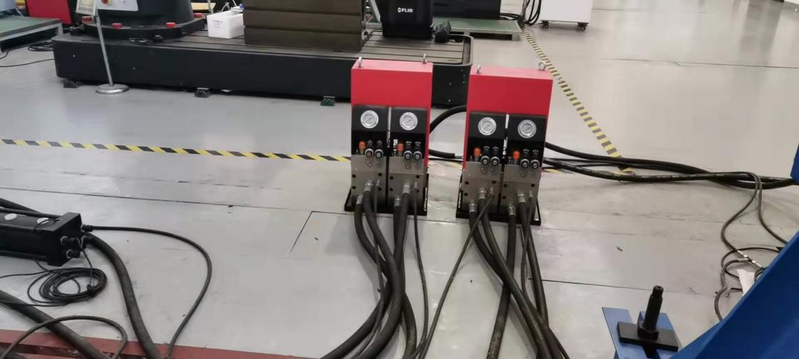
7.4 Oil distribution station (recommended addition, indicator and single actuator can be used separately)
The function of the oil separation module is to divide the output flow of the oil source into different routes and transport it to each actuator. (one drags two)
Oil separation module with computer control channel oil circuit opening and closing function, oil pressure storage function, precision filtration function.
The dynamic channel is equipped with oil pressure pulsation balance and oil pressure influence isolation device to balance the influence of dynamic pressure fluctuation of two dynamic channels on each other to the maximum extent.
With unloading function, when there is protection or other needs, the main oil line pressure can be quickly discharged to 0.
The pipe section is divided into hard pipe and hose. The hard pipeline part is mainly between the oil source and the oil distribution module, and the hose road is mainly between the oil distribution module and the actuator part.
The hard pipe is a high-strength precision seamless steel pipe, the outer surface of the steel pipe is treated with phosphating oil, and has high rust resistance and high pressure resistance.
The steel pipe is connected by a welded flange with a sealing ring. The elastic link is set at the special connection to eliminate the pipeline stress caused by the dimensional error and installation error, and improve the service life of the pipeline. The hose is an imported product with high safety and wear resistance.
Multichannel Sub-Station (HSM)
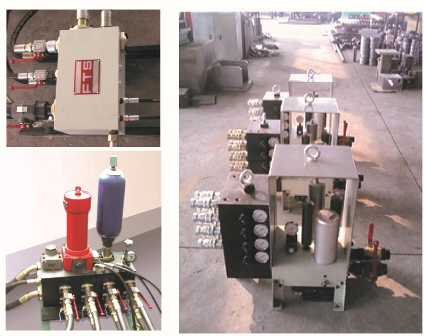
Multistage piping system
Adopt a centralized oil source, connect sub-stations between the equipment and the pipeline, and the flow rate is not less than 200L/min; The sub-station can adjust the pressure and can be displayed. There are P (high pressure oil port, 2 inches), T (low pressure oil port, 2 inches), R (oil drain port, M18*1.5) on the sub-station. The P and T ports are connected with SAE flanges. Port R is threaded.
Viscosity range of hydraulic medium: ISO VS32~46; Oil source operating temperature range: 15℃~55℃; Pipeline outlet hydraulic oil quality is less than or equal to NAS7. The sub-station should be configured with a filter, the filtering accuracy of the sub-station is 3 microns, equipped with a filter block signaling device, when the blockage occurs, the transmitter sends a signal, the filter element should be replaced immediately. The supplier is responsible for the piping between the sub-station and the equipment.
8. Configure the list
| No. | Name | Model and Specification | Quantity | Name of origin and manufacturer | |
| 1 | Host | Base | 30kn | 1 piece | self-production |
| Transom | 1 piece | ||||
| Upright | 4 pieces | ||||
| Hydraulic Lifting System | 1 set | ||||
| Hydraulic Locking | 4 pieces | ||||
| Horizontal Actuator Lifting Device | 4 pieces | ||||
| Fixture | 2 sets | ||||
| No. | Name | Model and Specification | Quantity | Name of origin and manufacturer | |
| 2 | Sensor 1 | Spoke type force sensor | 30kn | 1 piece | Ambrose |
| Sensor 2 |
Displacement sensor | AML300 |
1 piece | Resolution: 0.001mm |
|
| No. | Name | Model and Specification | Quantity | Name of origin and manufacturer | |
| 3 |
Servo power source |
High Pressure Internal Gear Pump | NACHI | 4 sets | Japan NACHI Corporation |
| Electric Machine | Southern Anhui |
1 set | |||
| High Pressure Hose, Joint | H | some | Imitation American Parker type H |
||
| Servo Valve | HY150B |
1 piece | HangYu |
||
| Printer | 1 set | Hewlett Packard |
|||
| High-Current System | 1 set | Beaconauto |
|||
| Controller | 2-channel |
2 sets | China |
||
| Computer |
I5/8g/1T |
1 set |
China. Advantech |
||
| Oil Dispensing Station |
F150 |
1 set |
self-produced |
||