SG30A microcomputer-controlled shock absorber indicator fatigue comprehensive test bench is mainly used for all kinds of automobile, air suspension air bag shock absorber, modified vehicle, SUV, armored vehicle, light truck, heavy truck, ATV and all kinds of motor vehicles used in the vibration absorber indicator test, line speed test, fatigue life test.
1. Product Overview:
SG30A microcomputer-controlled shock absorber indicator fatigue comprehensive test bench is mainly used for all kinds of automobile, air suspension air bag shock absorber, modified vehicle, SUV, armored vehicle, light truck, heavy truck, ATV and all kinds of motor vehicles used in the vibration absorber indicator test, line speed test, fatigue life test. Special fixtures can also be made to adapt to the fatigue test of special specimens.
2. Product pictures:
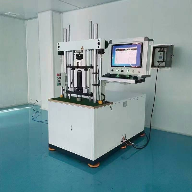
(Figure 1)
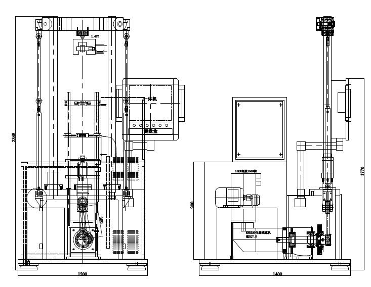
(Figure 2)
3. Description of equipment structure
The machine is single-station operation, the whole is a vertical double-column structure, by the frame, upper beam and lifting mechanism, damping force detection system, drive mechanism, shock absorber cylinder pressing mechanism, indicator and fatigue equipment, hydraulic system, acquisition card, computer, industrial control software and electronic control system, quick plug joint optional.
1. Frame: The use of industrial grade channel steel and steel plate welding machine and grow square frame, weld bead uniform and beautiful. With sufficient strength and rigidity, in order to ensure safe operation.
2. Upper beam and lifting mechanism: composed of beam, two beam guide column, two lifting hydraulic cylinder, beam locking mechanism, hydraulic pressure, etc. The hydraulic cylinder drives the cross beam up and down and hydraulically locks it automatically in the stop position, thus controlling the installation height of the equipment and making the test stroke located in the middle part of the shock absorber stroke.
3. Piston rod top tightening and pulling mechanism: composed of hydraulic cylinder, guiding and connecting mechanism, force sensor and fixture, etc., to achieve the piston rod clamping back to the working position.
4. Damping force detection system: composed of force sensor and manual clamping device. The force sensor is used for real-time monitoring of tensile and compressive forces during workpiece motion.
5. Drive mechanism: composed of servo motor, reducer, gear belt, gear belt wheel, bearing seat, spindle, crank, slider and guide device. The motor reducer provides power to the moving part. Through the transmission of the tooth belt and the main shaft, the power is transferred to the slider mechanism of the crank handle to realize the movement of the workpiece according to the sine.
6. Shock absorber cylinder pressing mechanism: composed of displacement sensor, pressing cylinder, upper pressing plate, guide column, base, etc. The upper press plate is driven by the oil cylinder to slide up and down to realize the compression of the shock absorber cylinder. The displacement sensor is used to monitor whether the guide press assembly stroke is in place.
7. Indicator tool: by the shock absorber ring fast clamping tool and the shock absorber cylinder clamping tool, the tool adopts quick change structure. The upper hanging ring adopts a general structure, and after manual placing, two kinds of mechanical tightening are adopted.
8. Hydraulic system: composed of oil tank, check valve, reversing valve, pressure regulator, motor, oil pump, air filter, etc., to provide power for workpiece clamping and upper beam lifting. Pressure regulating valve and pressure gauge are added respectively to control and display the oil pressure of the hydraulic system's guide jacking cylinder and lifting ring jacking cylinder.
9. Acquisition card: used for force and displacement signal acquisition and transformation.
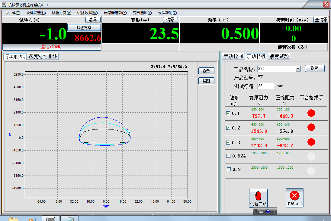
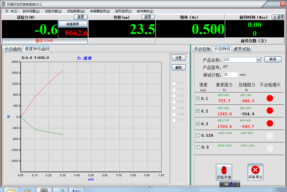
10. Computer (using win7 system) : used to receive the acquisition signal of the acquisition card, and through the installation of industrial control software for calculation, analysis, drawing P-S diagram and P-V diagram, display the maximum tensile and compression damping force, set, upper and lower limits, unqualified screen display alarm and install traffic light display.
11. Electrical control system: by servo motor driver, electrical components, electrical circuit and electric control box and other groups. Agreed. Manual and Automatic two operating modes, the device adds the origin switch, to ensure a key reset.
12. Software: shock absorber performance test system functions and characteristics:
1) System Settings saving function: the test system can save the Settings of force and speed;
2) Self-test function: can self-test the device to check whether the device is normal;
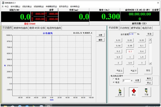
3) Operation adjustment function: move the displacement sensor housing up or down to zero the displacement sensor;
4) Sensor calibration function: force sensor, displacement sensor and speed can be calibrated.
5) Force sensor zeroing function: when the lower end of the force sensor installation fixture is replaced, and the force sensor zeroing is required before the first test area every day;
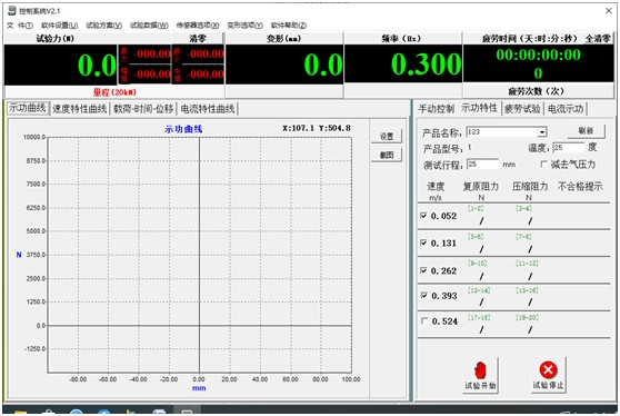
6) Single condition test function: the shock absorber can be tested in single condition, manual test or automatic test. After the experiment is completed, the experimental data can be saved, read and printed.
7) Multi-condition test function: multi-condition test can be carried out on the shock absorber, manual test or automatic test, after the completion of the experiment, the experimental data can be saved, read and printed.
8) Counting function: the number of shock absorbers tested every 24 hours (including the number of qualified products and unqualified products), and can be saved, read and printed.
9) Indicator results can generate reports (including data, graphics), and data is stored in Excle files.
10) Fatigue test (destructive test can be done according to the experimental requirements. Can reach the preset number of shutdown function, force value attenuation curve, peak detection, etc.)
11) Inductance test: under the same speed requirements, different currents or voltages can be given to test recovery and compression resistance.
12) Software reference interface:
4. Technical parameters of the equipment:
1. Maximum power value: 30000N
2. Speed: can be adjusted between 0.01~1m/s, the motor is a servo motor, higher accuracy, through the controller can be set at will the required speed, can also be set shortcuts, to achieve the convenience of use of common speed.
3. Travel: 0~150mm (manual adjustable), display test travel.
4. The maximum damping force: only 1m/s 10000N.
5. Rhythm: two speed points ≤12 seconds/piece;
6. Test accuracy: 1%FS
7. Test space: 900mm
5. Equipment production process description:
Install the tooling according to the production variety and adjust the stroke according to the test requirements → turn on the power supply of the main machine and the computer to enter the test program → on the part, press the start button → the cylinder top tightening device positions the workpiece → the driving mechanism drives the workpiece to start the indicator → The display system draws the indicator diagram respectively on the same interface and displays the maximum tensile and compressive damping force. Unqualified parts automatically alarm and install traffic light display → so alternating cycle work.
1. Different types of workpiece replacement indicator fixture.
2. Adjust the initial position of the upper beam for different lengths of workpieces.
3. Different stroke workpiece, adjust the eccentric position.
6. Quality control requirements:
1. The force sensor (measuring range 2T) itself repetition accuracy 1%FS.
2. Displacement sensor range: 0-200mm, its own repeated positioning accuracy ≥1%FS
3. Can set the upper and lower limits of force value, unqualified screen display alarm.
4. Can set the upper and lower limits of the guide pressure installation displacement, unqualified screen display alarm.
5. The detection force value error is 1%.
7. Process equipment requirements:
1. In the process of equipment manufacturing, the supplier shall provide Party A with 1 product tooling and drawings.
2. The performance of the machine shall meet the requirements of Party A's drawings.
3. The surface of the tooling should be treated with anti-rust treatment such as black or chrome plating.
4. The equipment should have a label.
8. Machine control and safety requirements:
1. The equipment with emergency stop button, increase the grating and start with both hands.
2. The electronic control system adopts programmable PLC control, control voltage DC24V
3. The rotating part of the equipment installation protection.
9. Device configuration list (Fill in according to the manufacturer's own configuration)
| No. | Component Name | Brand | Specifications |
| 1 | Host | BeaconAuto | self-developed |
| 2 | Servo motor and drive system | Huichuan servo | 25KW |
| 3 | Planetary reducer | Shanghai Fengxin | quiet type |
| 4 | vane pump | constant force hydraulic | VPE-F12D-10 |
| 5 | Solenoid valve | Shanghai Huayuan | 4WE6 |
| 6 | Temperature sensor | Guangzhou | -40 degrees ~150 degrees |
| 7 | hydraulic jacking cylinder | Tianjin Jiagang | CHTM-SD63*50N-S2 |
| 8 | High-precision load sensor | specially customized (shock-proof type) | 3T spoke type |
| 9 | Displacement sensor LVDT | Beijing Academy of Water Sciences | 200mm |
| 10 | board controller | BeaconAuto | self-developed |
| 11 | control software | BeaconAuto | Self-developed |
| 12 | All-in-one computer | Dell/Lenovo | standard |
| 13 | Printer | A4 inkjet/HP | standard |
| 14 | Strong electric appliances | domestic first-line brand | tentative |
| 15 | High-pressure oil pipe | import | tentative |
7. Use conditions and environmental requirements
1. Power supply voltage fluctuation range: 380±15%
2. Air source: ≥4bar, flow 20L/min
3. Working environment temperature: 5~40℃
4. The installation site is limited, the plane layout of the whole machine.
5. Hydraulic oil brand: N46