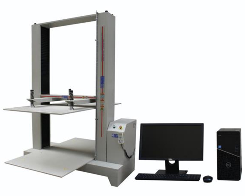
Carton Compression Testing Machine is suitable for corrugated boxes, honeycomb boxes, plastic containers and other packaging and packaging containers to withstand pressure, deformation, stacking test.
1. Design conditions
1) Product specifications: 32inch-85inch;
2) Power supply: three-phase 380V10% single-phase 220V 50Hz
3) Reserve 1 ohm ground point and 4 ohm ESD ground in the plant.
4) Outdoor environmental conditions: humidity 50%-90%RH, temperature -10-40℃.
5) Working conditions of clean workshop: temperature 23±2℃, humidity 60±5%RH
6) Backlight and front section of module assembly area cleanliness: 100k
7) The cleanliness of the module back section and module detection area: relatively clean
8) Maximum bearing weight: 50Kg (each tooling plate -PALLAT, without tooling and tooling plate), uniform throughout the line.
9) Compressed air (CDA) : 0.4-0.6Mpa.
10) Noise: the static noise at a distance of one meter is not more than 60dB, and the dynamic noise is not more than 75dB.
11) Safety protection and protection should meet the requirements of national standards and related products.
12) layout -layout: See the attachment for process diagram.
13) Clean room height: 3000mm
Packing box size reference:
| Category | Maximum size/mm |
| 32" | 900*170*550 |
| 39" | 1100*180*680 |
| 40" | 1100*190*690 |
| 43" | 1150*210*710 |
| 49" | 1300*220*810 |
| 50" | 1500*220*850 |
| 55" | 1550*230*900 |
| 58" | 1550*240*910 |
| 60" | 1600*250*980 |
| 65" | 1850*260*1100 |
| 75" | 1885*399*1218 |
| 85" | 2100*292*1301 |
2. Equipment use
1.1. This machine is suitable for corrugated boxes, honeycomb boxes, plastic containers and other packaging and packaging containers to withstand pressure, deformation, stacking test. Due to the servo motor drive, ball screw drive lifting and compression process is stable, low noise, no shaking, greatly improve the test accuracy and reliability.
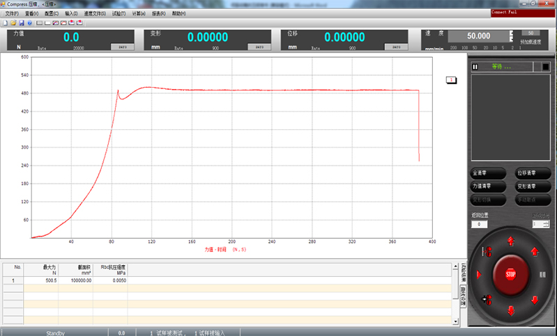
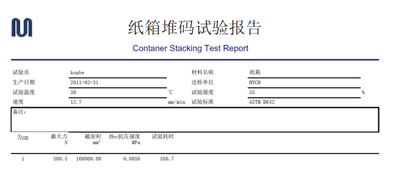
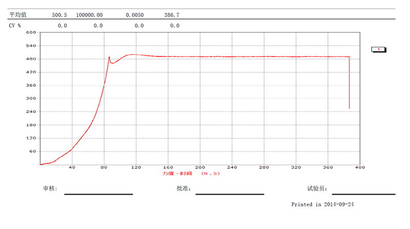
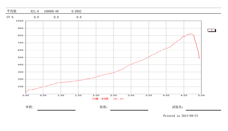
1.2. carton compression testing software, can do: stacking test (fixed load, fixed time, load fluctuation ≤0.25%F.S), compression test. Whole-process record force-displacement curve, force-time curve, deformation-time curve, can be stored, automatically calculated, and can be customized according to customer requirements of the special test report format for easy printing.
Applicable standards: GB/T4857.4 "Packaging - Pressure test Method for Transport Packaging", GB/T4857.16 "Basic Test for Transport Packaging - Piling Test Method using Pressure Test" equivalent to ISO2874, ASTM D642, GB/T16491, TPPI-T804, JIS-Z0212;
3. Technical parameters
| Model | RS-8401-10KN |
| Test items | Packaging container compression, stacking test |
| Compression capacity | 10kN (1000kgf) |
| Resolution | 1/500,000 |
| Effective force measurement range | 0.4% ~ 100% |
| Displacement resolution | 0.001mm |
| Deformation measurement range | 1% to 100%FS |
| Compression rate | 0.001~200mm/min |
| Accuracy | 0.5 class |
| Data acquisition frequency | 800 times /sec |
| Compressed space WxDxH | *1000x2000x1500mm |
| Volume - Host WxDxH | 1600x2000x2350mm |
| Weight | about 1350kg |
| Power supply | AC220V 50Hz 10A |
4. Main configuration
4.1. The use of Japanese Panasonic servo motor drive to overcome other power sources (such as hydraulic systems, ordinary motors, etc.) uneven pressure, large mechanical resonance, large noise, positioning accuracy is not high, uneven lifting speed and other shortcomings;
4.2. Taiwan ABBA precision ball screw, high precision, high transmission efficiency (3 times that of trapezoidal screw), high rigidity, low deformation, low noise;
4.3. Adopt Japan LINE® 2500rp high-pulse photoelectric encoder to measure the deformation, and the four-quadrant acquisition resolution of the high-speed circuit system is 1um; The effect of jitter or direction change at low speed is completely solved, and the displacement resolution of the testing machine is increased by four times.
4.4. Use the US TRANSCELL high-precision explosion-proof pressure sensor, the measurement accuracy is as high as 0.02%F.S, low creep, long life;
4.5. Unique manual box design set: rise, fall, run, stop, zero, micro-movement (up), micro-movement (down), easy to hold the specimen when the upper plate positioning and calibration of the machine, without computer control;
4.6. The machine is equipped with: stroke mechanical limit protection, software force upper limit protection (to prevent sensor damage caused by false action), over current (over current), lack of phase (lack of phase sequence), too much torque, overheating and other protective devices;
4.7. Material: The upper, middle transverse and upper and lower clamping plates are made of high steel die steel (45#) after grinding, with high rigidity and low deformation.
5. Control software: Professional carton compression/stacking test software
5.1 Multi-pass load element and deformation configuration (optional):
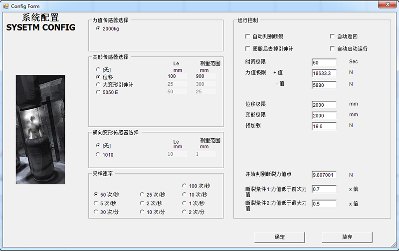
The test software developed specifically for carton compression and stacking test is easier and more targeted than the previous generation software. Taking stacking test as an example, only need to set the force value retention and holding time to do stacking test.

5.2. Stacking test method editing (customers can set by themselves) :
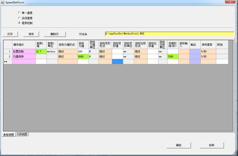
Only need to set the preloading force 220N (GB/T4857 has provisions), the target stacking load value (such as 5000N), stacking time (such as 7200sec=2 hours), the operation is simple
5.3. Professional report analysis can be printed or saved:

6. Other
6.1. Party B shall carry out installation and commissioning in the factory. After completion, Party A's factory shall pass the inspection before delivering the goods. The goods shall be packed in strict accordance with the requirements of Marine packaging.
6.2 After the equipment enters the factory, Party B shall provide Party A with technical support and training in any form required for installation and commissioning;
7. Safety and quality requirements
1, equipment safety requirements:
1.1. Equipment transmission mechanical parts (such as line body belt and roller, sprocket and chain, etc.) and personnel easy to contact parts (such as elevator entrance) need to increase the protective cover or guardrail, considering the anti-stay, personnel can not contact the dangerous transmission part;
1.2. Three-position five-way solenoid valve is adopted for vertical shift and load shifting equipment (cylinder mode), and emergency stop switch is set separately for vertical shift. After the emergency stop switch is triggered, the vertical shift stops in the original position;
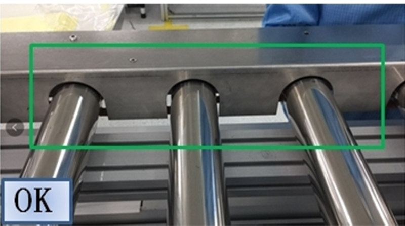
1.3. Mechanical deadstop and corresponding deadstop detection device should be set for elevators with lifting action, so that maintenance personnel can prevent sudden fall and smash injury of lifting unit after entering the equipment (refer to the following photos);
1.4. Safety maintenance door is set up for the elevator to facilitate personnel to clean 5S and repair, and safety grating should be added to the elevator inlet and outlet to prevent personnel from being injured by mistake. Set the safety access door, and set two sets of magnetic safety switches for each access door. All security switches enable the ByPass function, which can be set only by password. The ByPass automatically switches to the use state 3 minutes after the security door alarm function is disabled.
1.5. Suspension (such as ion fan, light frame, operation manual hanger) parts must be fixed firmly, suspension parts when the weight is large to avoid a gap or loosening at the link between the corner part and the profile, you can consider the screw through the profile fixing method;
1.6. Safety mark:
1.5.1 Add photos according to different positions and confirm with Master Tang
1.5.2
1.7. The whole periphery of the equipment shall have the equipment shell frame, and at least four groups of footing shall be firmly fixed. The equipment security door shall be equipped with access control; The paint iron plate (thickness ≥1.5mm) is used below 1m from the ground, the paint iron plate is 150mm from the ground, which is convenient for 5S cleaning, and the endurance plate is 5mm or above 1m. (Refer to the photo below)
1.8. The equipment in the stopped state of accidental power failure should not change and move, and the loss and change of power will not cause accidental injury to the person and the product;
1.9. Equipped with a combination switch (start, emergency stop, reset) in the position convenient for personnel to operate, to deal with the emergency situation of the equipment, the touch screen displays the alarm information of the emergency stop switch position;
1.10. Each single device should have protective stop function, such as protecting photoelectric, grating, etc.;
1.11. The device shall have good grounding protection, leakage protection, overload protection and anti-static grounding. Each cable body shall be grounded repeatedly at least three times. The color of the anti-static grounding cable shall be yellow green, and the device grounding shall be black.
1.12. Lay two single-core 10mm² yellow and green antistatic copper cables across all wires (or equipment), and isolate them from the grounding ground of the wires. Lay one 10mm² black grounding main line (all wires), and the tension of the antistatic copper cables and grounding main line can be adjusted. The connecting part of the device shall be equipped with a ground jumper cable.
1.13. Noise: static noise at a distance of one meter is not more than 60dB, dynamic noise is not more than 75dB;
1.14. Configuration of surveillance cameras: at least one set of cameras should be added to the locations of security organizations and product quality assurance organizations to facilitate the tracing of causes when anomalies occur. The retention time of surveillance videos is 30 days;
1.15. During the trial operation phase of the project, Party B shall conduct safety training for all users and maintenance personnel of our company. The training contents shall include safety precautions of all mechanical and electrical parts within the construction scope, and the training contents and trainees shall be recorded as the basis for final acceptance.
2, quality requirements:
2.1. Under the transmission mechanism, such as belt, double speed chain, chain, etc., the ash box must be considered to effectively reduce the quality risk of foreign matter; At the same time, all the single equipment is laid under the 2.5mm thick stainless steel plate, which is easy to clean and reduce foreign bodies;
2.2. For the tooling pallet in contact with the product, a foreign body adsorption device should be added on the running route, which can be magnets or blowing duckbills to ensure that the tooling surface is free of large particle foreign bodies such as metal causing product scratches;
2.3. For product clamp equipment, the flexibility of the clamp arm should be fully considered, and the power supply board, wall mount bracket, PCB board and other avoidance areas of the product should be avoided. If the cylinder is used, the clamping force can be adjusted flexibly. At the same time, protective materials such as silicone sleeves or anti-static sponges are used to avoid the appearance of the product.
2.4. The adsorption mechanism must have the function of power failure and self-maintenance to prevent the product from falling and causing scrapping when the equipment is abnormal or emergency power failure;
2.5. All the contact mechanism with the product should be protected with silicone, anti-static sponge, flocking cloth, etc., and it is not allowed to contact the product with hard materials such as metal, so as to avoid scratching and squeezing of the product;
2.6. Reserve 10% of the mechanical structure size range of all contact products to prevent product damage beyond the normal range of the mechanism;
2.7. The photoelectric detection of the product in place in the design of the mechanism should not be less than 2 groups, with anti-leakage detection function, so as to avoid the omission of the equipment on the operation of the product;
2.8. During the trial operation phase of the project, Party B shall conduct spot inspection on quality-related items with our technical personnel, quality personnel, usage management personnel and equipment maintenance personnel, and record the inspected items, problems, rectification countermeasures and progress as the basis for final acceptance;
2.9. Do a good job of protecting the direct contact parts of the single equipment and the product. If the product is transported by pneumatic transmission or pressing, it is necessary to add a pressure regulator to install a visual pressure gauge;
2.10. Rely on the suction cup to carry the panel, gasket and other mechanical structures, the nozzle distribution distance is reasonable, according to the size of the nozzle vacuum switch can be controlled in the man-machine interface, the production size is adjustable, and the negative pressure value can be adjusted.
8. Common norms
1. Energy saving part:
1.1. The electrical meter (with 485 communication interface) should be added to the technical modification line according to the module, the whole machine, packaging, conveying line, palletizing, etc., and the electricity consumption can be counted in sections.
1.2. Technical improvement line and large automation equipment, if there is no compressed air meter, need to add a group of compressed air flow meter (with 485 or network port communication interface), which can display the gas consumption in real time.
1.3. All the lighting parts of the line body are made of LED energy-saving lamps, and Hisense designated brands are used, and the illuminance meets the illuminance requirements of the line work position.
1.4. The SMC solenoid valve (with bypass) is added to the main air path of the equipment to realize the automatic air cut off function after the power is cut off to the wire body in the man-machine interface.
1.5. Midwifery belt shall be required at the connection of pipe fittings, and air leakage shall be eliminated in the new line body and equipment.
1.6. The wire body and the blowing part of the equipment, such as blowing foreign bodies, duck mouths, ion rods, etc., need to increase the solenoid valve control, and only work when the product passes and the air needs to be blown.
1.7. The wire body and equipment software design are reasonable, and the motor is not allowed to have idle phenomenon.
1.8. The pneumatic components of the technical transformation line body are specified to use the SMC brand, if there is a special brand demand, it is explained in the fifth part of the parts brand.
1.9. The selection of equipment electrical components shall conform to the specified range of Hisense, select models with energy-saving characteristics, and match the power with the load demand. If there are special models or special parts, please communicate with Hisense to confirm.
2. Requirements for the overall structure of the line body
2.1. Height of working surface 850mm, adjustable range of ground Angle: ±20mm.
2.2. The structure of the wire body is modular assembly of aluminum profiles and stainless steel materials. The steel used must be chrome plated. And press the free section seam to seal strip.
2.3. There should be good grounding protection, leakage protection, overload protection and anti-static grounding, and at least three repeated grounding points in each section of the cable body. The color of the anti-static grounding cable is yellow green. The device is grounded in black and separated from the electrostatic discharge (ESD) ground. The diameter of the grounding cable must meet the requirements of related standards. A ground jumper cable is required for connecting devices.
2.4. Each station and pallet stay position or product contact position must be set up electrostatic conduction device, and ensure that its reliable grounding.
2.5. Each moving part is flexible, stable, safe and reliable, no crawling, jumping phenomenon, no abnormal sound, the workpiece has no collision swing phenomenon, noise: static noise at a distance of one meter is not greater than 60dB, dynamic is not greater than 75dB.
2.6. The transmission machinery part is protected by stainless steel to avoid injury caused by personnel contact.
2.7. Each drive and transmission parts are well lubricated, without oil leakage and dust.
2.8. Line body coloring: aluminum alloy and stainless steel.
2.9. The elevator entrance and exit are equipped with yellow protective guardrail and warning signs. If the guardrail is not removed, any part of the operator's body can not enter.
2.10. The selected components are unified under the same conditions, such as the main line motor, reducer, pneumatic three major parts, etc., the same model is selected.
2.11. Input and output signals should be marked on each execution component to facilitate debugging and troubleshooting. The man-machine interface should have all I/O signal points, which can be easily queried
2.12. The manufacturer's nameplate is not allowed in any position of the production line, and the nameplate of all purchased parts is not allowed to be damaged.
2.13. All parts and accessories provided by the bidder shall have production license and safety certification mark. Photocopies of certification documents if required.
2.14. Install ESD ground cables for all cables.
2.15. The section of the profile shall be equipped with a cover, and the profile trim shall be installed on the side.
2.16. All fluorescent lamps are equipped with independent switches.
2.17. The materials used in the equipment must meet the requirements of the clean room and must not rust.
2.18. The shape and specification of the single equipment guardrail are unified, and the iron plate below is transparent acrylic plate above.
2.19. Mechanical design and installation should be convenient for subsequent maintenance and replacement of parts.
3. Power supply:
A. Phase 3 AC380V 50HZ
B. One test air source: 4-6kg/㎝²
C. Electrostatic grounding: yellow and green cables
D. Device grounding: black line
4. Air piping: Each line body is installed with an air pressure triplet bilateral air piping ∮1 "(stainless steel pipe) All the external pneumatic parts of the ground pipe are made of 3/8" metal C-type quick connector (with male connector) placed on the inside of the conveyor on the standing foot, the switch (ball valve)+ ∮8 PU hose quick connector/head tail.
5. Each branch of the trachea junction should mark the station where the trachea goes towards and ends, and the trachea should be horizontal and vertical.
6. 24V power supply is used to control the line body of the electronic control system.
5.1PLC control system
5.1.1.PLC with Mitsubishi Q series, installed in the main cabinet of the on-line body head, and the memory must be reserved 10%; Input and output points must be reserved 10%, at the same time to the terminal, and mark the PLC point line number.
5.1.2. All signal lines should be clearly marked by bushing, and the number tube should be printed, not handwritten.
5.1.3. The input signal and output signal wires are of different colors and have a diameter of 0.5mm2.
5.1.4. All output modules must have a separate fuse with light (fuse 2A).
5.1.5. A light fuse (fuse 2A) is required for all +24V outlets of the PDC.
5.1.6. All electrical components in the control cabinet shall be marked with output point numbers and control objects.
5.1.7. The program must be written in the programming software and annotated in Chinese, and edited and annotated according to functional differences. The holding relay should be used as far as possible when writing the program.
5.1.8. After the debugging of the program is completed, the debugging program and useless program statements must be deleted. Different line body procedures must be consistent.
5.1.9. All anti-static wires must be connected in series and can be monitored for breaking. All joints shall be welded with soldering iron, and the Tenderee requires the use of soldering iron welding.
5.1.10. All motors and cables shall be connected with inlet closed terminals and shall not be wrapped with adhesive tape. Wiring should be beautiful and practical, as far as possible to use plastic cable trough, wiring method shall be subject to the requirements of the tenderee.
5.1.11. The load capacity of all cable troughs shall not exceed 70%.
5.1.12. There must be stop-line protection procedures in all places where there is a risk of falling in the lift and moving car. There are protective measures and signs.
5.1.13. The control mode shall have automatic mode and manual mode function. In manual mode, each action operation shall have interlock protection, and no collision may occur.
5.1.14. In the jacking, the lift must have a junction box for easy maintenance. The distance between the terminal block in the distribution box and the terminal block and the distance between the terminal block and the edge of the distribution box should not be less than 100mm. The distribution box cover is hinged for easy disassembly. Each junction box has its own I/O diagram. The inlet and outlet cable boxes are locked.
5.1.15. The lift shall be equipped with an independent distribution box, and its control part shall be placed in this distribution box to reduce interference.
5.1.16. Install a Mitsubishi latest color 10.4 inch touch screen on the main distribution cabinet. The touch screen must be designed to display more than 100 kinds of abnormal faults and handling methods of the line body, and the power cannot be lost, including (line body faults, lift faults, system faults, PLC faults, frequency converter faults, etc.).
5.1.17. The Software shall design a password setting interface.
5.1.18. After the debugging of all programs, provide a backup of the tenderer's CD-ROM, and the password of the program shall not be set.
5.2 Strong power system
5.2.1 Lay two single-core 6mm2 yellow-green anti-static copper cables across the entire line, isolate them from the ground wire of the cable body, and hang clear anti-static labels every 5 meters. The specific positions are determined by the tenderer on site. And electrostatic copper wire tension can be adjusted.
5.2.2 All power lines should be marked on the entrance side and the exit side of the same pipeline to facilitate inventory.
5.2.3 The emergency stop switch shall be set up in the designated position of the wire body, which shall be hung with a clear emergency stop sign and protected by a plexiglass cover to prevent misoperation. The specific position shall be determined by the bid inviter on site.
5.2.4 Power starting shall be controlled by segmented delay, and each power shall independently correspond to an output point.
5.2.5 All motors shall be protected by heating relays and all motors shall be protected by ground.
5.2.6 All power wires meet load requirements for multiple copper wires.
5.2.7 Each line body shall be reliably grounded at more than three safe ground points, which shall be marked on the drawing.
5.2.8 The start and stop of the wire body should be indicated by corresponding indicators.
5.2.9 Socket and lighting control need to install leakage switch, socket current 10A/ group.
5.2.10 The device must be labeled with a danger warning label.
5.2.11 Air switch with leakage protection device
5.2.12 Set the total leakage detection device. The leakage current limit can be set.
5.2.13 Cable troughs must be secured to the feet.
5.2.14 The switch for each station shall be 22 lock female (including emergency stop switch).
5.2.15 The SCRAM switch on the cable body must have a yellow protection cover (notched) and a Chinese identifier with black characters on a yellow background.
5.2.16 All labels must have Chinese labels.