WLB-10KN electronic puller adopts servo control system, can realize uniform displacement loading and uniform force loading two loading modes, high efficiency and good stability.
1. Main use and scope of application
WLB-10KN electronic puller adopts servo control system, can realize uniform displacement loading and uniform force loading two loading modes, high efficiency and good stability. With dual sensor function, the measurement range is wider, the accuracy is higher, and the use is more flexible and convenient. Touch screen control, man-machine operation interface is friendly. The drawing instrument is equipped with travel limit and overload protection function of positive and negative force value, which can prevent the damage of equipment caused by misoperation.
It is suitable for tensile and bonding strength test of dry mixed mortar, insulation material, ceramic wall and floor tile adhesive, laminated building paint and putty used for building exterior wall. It conforms to the bonding strength test of various building materials stipulated by JC/T547-2005, GB/T9779-2005, JG/T157-2004.
Main features:
1) Touch screen control, user-friendly interface.
2) Servo drive, continuous uniform displacement loading and uniform force loading.
3) With dual sensor function, the standard configuration is one sensor.
4) Fast lifting and one-key automatic return function when there is no load.
5) Overload protection function of travel limit and positive and negative force value.
6) Fast positioning in X-Y direction, especially suitable for the detection of multiple samples on a test plate.
7) Equipped with a single point clamp, convenient for single sample testing.
8) Joint T-card head to facilitate the positioning and loading of specimens.
9) Movable press to prevent bending and deformation of the test material. (non-standard)
2. Main technical indicators
1) Maximum experimental force: 10000N
2) Load resolution: 0.1N
3) Effective detection range: 1%-100% of the maximum experimental force
4) Load measurement accuracy: within ±0.5% of the indicated value
5) Drawing method: force value control, displacement control and other control methods
6) Drawing speed range: 0.1mm-300mm /min
7) Specimen width range: 70-500mm
8) Maximum thickness of the specimen: 50mm
9) Maximum stroke of test head: 100mm
3. Working environment conditions
3.1 Within the range of room temperature 100C ~ 350C, the relative humidity is not more than 80%;
3.2 Install it correctly on a solid foundation or workbench with a levelness of 0.2/1000;
3.3 In an environment without vibration, corrosive media and strong electromagnetic field interference;
3.4 The fluctuation range of the power supply voltage should not exceed ±10% of the rated voltage.
4. Main structure
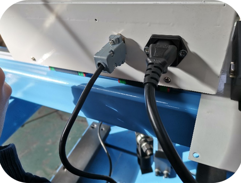
4.1 Connecting Power Supplies
As shown in the figure, insert the random power supply into the power port, turn on the front power button, and the sensor cable is connected before delivery.
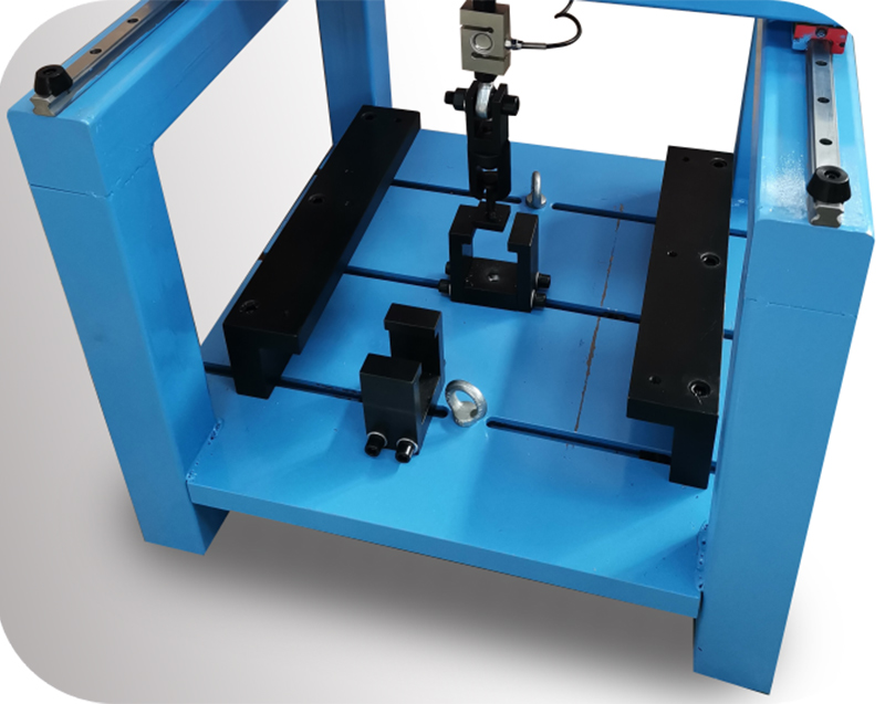
4.2 Adjustment of experimental position
As shown in the figure above, according to the number of test blocks, you can install a single point tensile fixture (random with 10 pieces), fix the position of the fixture, and then manually adjust the position of the pull head, test, tensile chuck is spherical universal, can be automatically aligned, suitable for various placement positions.
There is a [power switch] button at the right end of the device to switch on or cut off the device and the external power cover plate red [emergency stop switch], green [power indicator].
After the host is powered off, rotate the [power switch] button, the system is powered on, and the green [power indicator] light is on. The device can run.
In case of emergency, press the red [emergency stop switch] to cut off the power supply of the host.
5. Installation and adjustment
5.1 Take the equipment out of the package and check whether there is any collision or damage during transportation.
5.2 Place the equipment on a solid platform or cement platform, and adjust the level so that it is in a horizontal position (levelness 0.2/1000);
5.3 The power supply system shall be 220VAC±10%/50Hz, and shall have reliable grounding measures.
6. Use and operation
6.1 Preparations:
6.1.1 Connect all cables of the device correctly, and then power on.
6.1.2 Preheat 5min;
6.1.3 Clear the test force display window to zero.
6.2 For specimens of different specifications, please replace different fixtures.
6.3 Introduction and description of each operation button are displayed on the device screen
Operation interface diagram (as follows):
6.3.1 Functions of the Face key:
Liquid crystal display: display force value, peak, displacement, speed, prompt, test curve, etc.
The LCD screen is a touch screen, and all the functions of the test can be completed by clicking the text or picture on the LCD screen.
6.3.2 Details:
The following details the display and function of each screen, interspersed with the use of buttons.

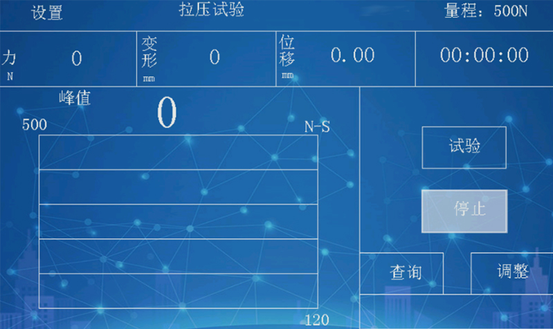
This is the screen directly entered after the boot, click on the screen, or click any key. The next screen is displayed, as shown in Figure 2:

In Figure 2, there is a * before "tensile test", indicating that the currently selected test method is a tensile test.
Clicking on any line on the screen indicates that the corresponding test method is selected. The < Rise >< fall > key in the keyboard can also be used to select the test method.
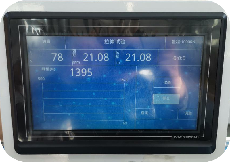
Here it is assumed that "tensile test" is selected, click OK on the screen or press the < Test > key to enter the next page, showing as shown in Figure 3:
In the picture shown in Figure 3, click "Test" or press the < test > key to start the tensile test process, and automatically end according to the conditions that have been set. Click the force box, deformation box and displacement box respectively to clear the execution force, deformation and displacement. Press the "Clear" key to clear force, deformation and displacement at the same time. Click "Query" to query the test results, press < print > key can also query the test results. Click "Adjustment" to display the screen in Figure 4, and you can adjust the position of the clamp of the beam clamp.
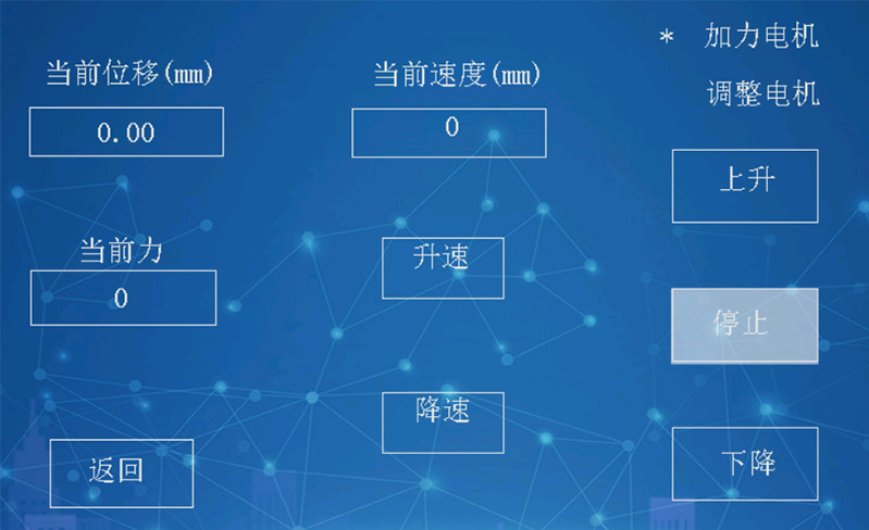
In Figure 4, click "speed up" and "speed down" to change the speed, and the < Switch > and < print > buttons can also change the speed.
Go back to Figure 3, click Settings in the upper left corner of the screen, or press < Settings > to switch to the screen into Figure 5:

In Figure 5, click "Test method selection" to switch to the screen as shown in Figure 2.
Go back to Figure 5, click "System calibration", prompt to enter the password, as shown in Figure 6:

Enter password 111 and click OK to enter Figure 7:

Three parameters: force, displacement, speed must be calibrated before use, otherwise inaccurate.
Among these three parameters, the calibration sequence should be displacement first, then speed, and finally force.
Two concepts: displacement and deformation.
Displacement is how far the test beam moves.
Deformation is the deformation of the specimen after being stressed, and the deformation can be measured by a special extensometer or by displacement. Taking compressed rigid foam as an example, during the downward movement of the upper indenter, the displacement continues to increase and the deformation is zero before contact with the specimen; after contact with the specimen, the deformation increases and the displacement also increases, and the total displacement minus the empty stroke before contact with the specimen is the deformation. This is the basic principle of measuring deformation by displacement.
The main control board supports three pulse input channels, namely pulse 0, pulse 1, pulse 2.
Pulse 0 is connected to the motor output pulse on the circuit board, for the stepper motor or AC servo motor, there is a motor drive pulse, pulse 0 counts, pulse 0 reflects the number of steps of the motor rotation, the motor rotation drives the beam to move, the pulse 0 is proportional to the displacement.
Pulse 1 and pulse 2 are complete orthogonal encoder interfaces with external pin inputs.
Click "Calibration displacement pulse" to display Figure 8:
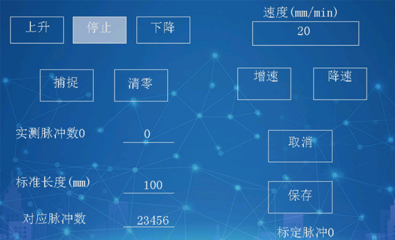
Measuring displacement requires a ruler or dial indicator.
Input any speed (when the speed is not accurate and unnecessary), the motor rises or falls to start the motor, take the ruler as the standard, let the beam move a certain distance, such as 20 mm, view the measured pulse number, assuming 2400, then the standard length is filled in 20, the corresponding pulse number is filled in 2400, click save, the displacement calibration is completed.
The calibration of encoder 1 and encoder 2 is similar and will not be described again.
Click "Calibration Speed" in Figure 7 to display as shown in Figure 9:
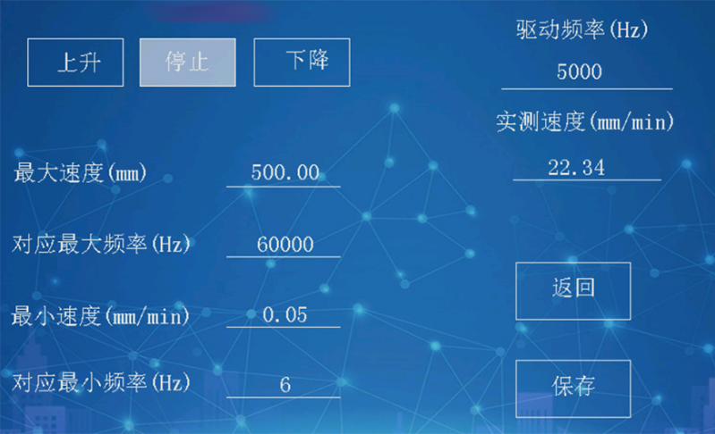
In Figure 9, input any drive frequency, such as 10000, click up or down, and check the measured speed three seconds later. If the measured speed is less than the maximum speed required by the device, modify the drive frequency and try again until the measured speed is greater than the maximum speed required by the device. Assume that the measured speed is 504 when the drive frequency is 64000.
Then stop, fill in the four numbers on the left, the maximum speed is 504, corresponding to the maximum frequency is 64,000, the minimum speed is 0.05(0.05 is 504 divided by 10000), the corresponding minimum frequency is 6 (6 is 64,000 divided by 10000). The speed ratio is calculated at 1:10,000.
Click on "Calibrating force sensor" in Figure 7, which displays as shown in Figure 10:

In Figure 10, prepare the standard dynamometer, fill in each point force according to the measuring range of the force sensor first, assuming that the measuring range of the sensor is 500N, then the force points can be 10,20,50,100,200,500, must ensure that the forces are arranged in ascending power, and the sixth force is the measuring range of the sensor. When the sensor is not stressed, click < Clear > to clear. Increase the force, check the standard dynamometer, when the force reaches a point, click "capture" on the screen, when the six force points are captured, click "Save".
In Figure 7, click "Calibrate other force sensors" to display as shown in Figure 11:

The machine can support another 3 force sensors in an interchangeable form, and the calibration method is similar to the first force sensor, so it will not be described again.
Click "Help" in Figure 5, and the help screen will be displayed, mainly the definition of each connection.
Select a test method in Figure 2 and click "Set" to enter the parameter setting page of the test method.
These parameters are called setup parameters, and the parameters described in the previous calibration are called calibration parameters.
The calibration parameters are set by the factory to determine the accuracy of the instrument, and the user cannot modify it at will, so it is password protected. The setting parameters can be modified by the user according to the usage. These parameters do not affect the accuracy of the device. No password required.
The following takes the tensile test as an example. The setting parameters of the tensile test are shown in Figure 12 to Figure 19

Figure 12
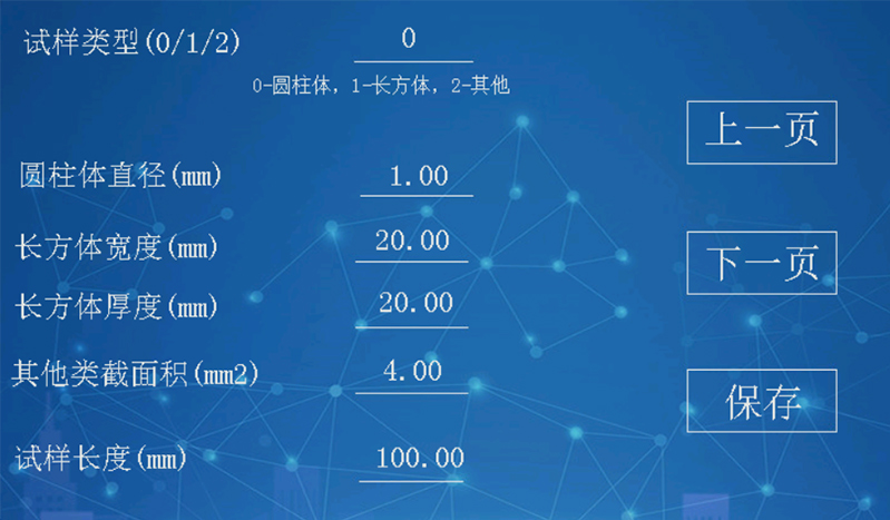
Figure 13
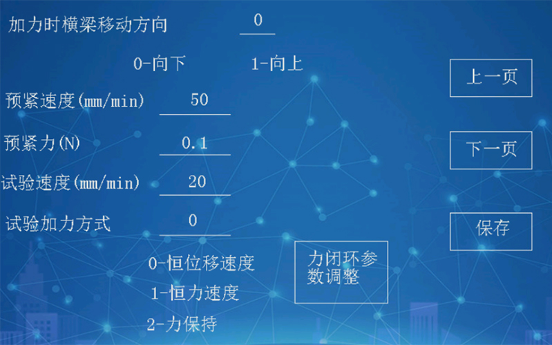
Figure 14
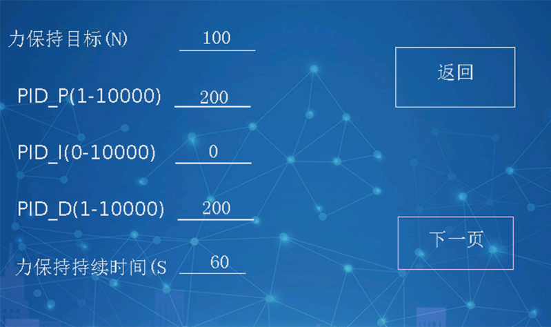
Figure 15

Figure 16
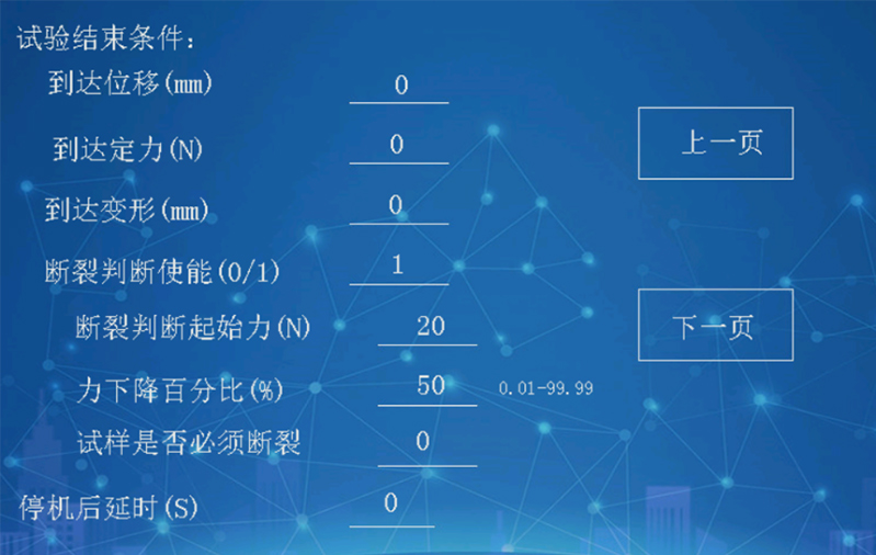
Figure 17
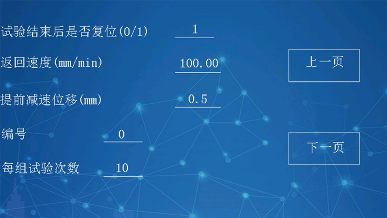
Figure 18
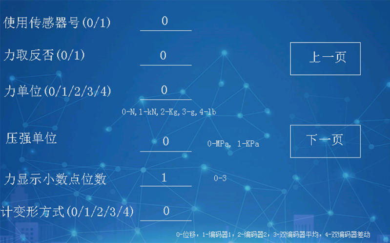
Figure 19
From Figure 12 to Figure 19, the parameters are set, which are described as follows:
The sample type is divided into three types. If the sample type is 0, the diameter parameter is valid, and the system will automatically calculate the cross-sectional area according to the diameter
If the sample type is 1, the width and thickness parameters are valid, and the system will automatically calculate the cross-sectional area according to the width and thickness.
If the sample type is 2, the cross-sectional area of other types is valid.
Force divided by cross-sectional area is equal to strength. The cross-sectional area is correct and the strength is correct.
Sample length is used to calculate elongation.
The low and high points of the elastic segment are used to calculate the elastic modulus (see GB/T228-2010). The two worth specific sizes are related to the sample. In general, the low point should be set at about 15% of the maximum force, and the high point should be set at about 30% of the maximum force, so the maximum force value should be estimated before the test. Set these two points according to the estimated maximum force. (Computer software can record the whole test process, no need to estimate)
Afterforce movement direction 0- down, 1- up
Start displacement speed, if the method of applying force is constant displacement speed, then here is the test speed.
If the pretension force is set to 50N, it means that the sample becomes straight when the force is 50N, and the starting point for calculating deformation is 0.1N by default
Force mode: Constant displacement speed, stepper motor and AC servo motor can provide the default force mode.
Constant force speed, this way requires the use of force feedback, also known as the force closed-loop algorithm, there are a variety of force closed-loop algorithms, here is the use of PID algorithm, need to set PID parameters in advance. The process of setting appropriate PID parameters is called PID parameter tuning.
Click [Force closed loop parameter Adjustment] in Figure 14 to display Figure 20

Constant force maintenance also uses PID algorithm, as shown in Figure 21

Note: In tensile test, the constant force retention method does not work, only in the force retention test.
7. Precautions
7.1 Before starting the system for the first time, check the accuracy of cables and input power supply. The power supply is 220V±50Hz and properly grounded.
7.2 Before the test, please set the test parameters correctly to ensure the accuracy of test data.
7.3 During the test, please do the test according to the correct method.
8. Common faults and troubleshooting
| Therefore, the appearance is blocked | Cause and treatment |
| No display is displayed after the device is powered on | Controller power cord, safety, switch, etc |
| Start no action | Host power supply, safety, switch, control cable |
| After loading, the test force is not shown | The sensor is properly connected |
| Force stability | Check system ground cables |
| Long sound alarm | The sensor is overloaded or the sensor line is broken |